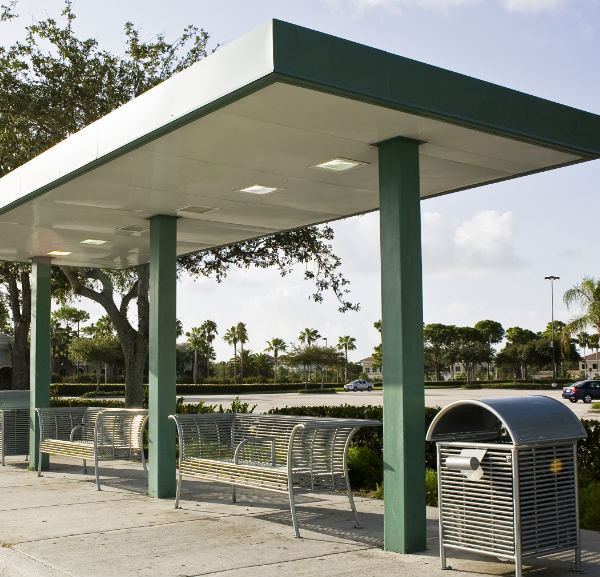
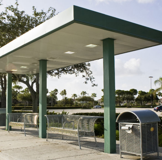
TRANSIT COVER CANOPY
Model: CAN-832-OFFSET
Features
-
Steel construction
-
Built in drainage system
-
Custom designed to meet your width & length requirements & can be offset as shown in picture
-
Fascia height varies to enclose structure
-
20ga Deck/ceiling available in bronze or white with smooth or embossed finish
Applications
-
Waiting shelter
-
Covered walkways
-
Building entries
-
School pick up/drop off entries
-
Covered walkway between buildings
Steel
Made In The USA
An alternative to a shelter when you are looking for open coverage is our transit canopy, which can be designed to meet your dimensional & height requirements. The canopy shown is offset to allow for clear foot traffic and lighting for 24 hr use. Benches are also available upon request. This design does require foundations to be set in advance to support the steel structure.
The BIM Object(s) are filled with data and they can easily be downloaded, customized for your commercial project.
PART 1 GENERAL
-
1.1 SECTION INCLUDES
- Freestanding, pre-engineered metal canopies including concrete foundation, steel framing, metal roof, roof drains and leaders, fascia components, and metal ceiling and accessories.
-
1.2 RELATED SECTIONS
** NOTE TO SPECIFIER ** Delete any sections below not relevant to this project; add others as required.
- Section 03300 - Cast-In-Place Concrete: Concrete islands and curbing.
- Section 02870 - Bollards: Metal, concrete, and stone bollards.
- Section 05500 - Metal Fabrications.
- Section 07900 - Joint Sealers.
- Division 15 - Plumbing: Plumbing services and connections.
- Division 16 - Electrical: Electrical wiring and connections.
-
1.3 REFERENCES
** NOTE TO SPECIFIER ** Delete references from the list below that are not actually required by the text of the edited section.
- American Institute of Steel Construction, Inc. (AISC): AISC 360 - Specification for Structural Steel Buildings (copyrighted by AISC, ANSI approved).
- American Society of Civil Engineers (ASCE): ASCE 7 - Minimum Design Loads for Buildings and Other Structures (copyrighted by ASCE, ANSI approved).
- American Welding Society (AWS): AWS D1.1 - Structural Welding Code - Steel (copyrighted by AWS, ANSI approved).
- ASTM International (ASTM):
- ASTM A 36/A 36M - Standard Specification for Structural Steel.
- ASTM A 307 - Standard Specification for Carbon Steel Bolts and Studs, 60,000 psi Tensile Strength.
- ASTM A 325/A 325M - Standard Specification for Structural Bolts, Steel, Heat Treated, 120/105 ksi Minimum Tensile Strength.
- ASTM A 500/A 500M - Standard Specification for Cold-Formed Welded and Seamless Carbon Steel Structural Tubing in Rounds and Shapes.
- ASTM A 572/A 572M - Standard Specification for High-Strength Low-Alloy Columbium-Vanadium Steels of Structural Quality.
- ASTM A 653/A 653 M - Standard Specification for Steel Sheet, Zinc-Coated (Galvanized) or Zinc-Iron Alloy-Coated (Galvannealed) by the Hot-Dip Process.
- ASTM C 1107 - Standard Specification for Packaged Dry, Hydraulic-Cement Grout (Non-Shrink).
- National Association of Architectural Metal Manufacturers (NAAMM): NAAMM MFM - Metal Finishes Manual.
- National Fire Protection Association (NFPA): NFPA 70 - National Electrical Code (copyrighted by NFPA, ANSI approved) - hereinafter referred to as NEC.
-
1.4 PERFORMANCE REQUIREMENTS
- Structural Performance: Provide pre-engineered canopies capable of withstanding the effects of gravity, wind, seismic, thermal and other project specific load conditions as required by the current building code for the site-specific location where Canopy is installed:
- Uniform pressure as indicated on drawings - minimum design wind load per ASCE 7
- Or Project specific design requirements (to be provided by owner prior to canopy design)
- Thermal Movements: Provide pre-engineered canopies that allow for thermal movements resulting from the following maximum change (range) in ambient and surface temperatures by preventing buckling, opening of joints, overstressing of components, failure of joint sealants, failure of connections, and other detrimental effects. Base engineering calculation on surface temperatures of materials due to both solar heat gain and nighttime-sky heat loss.
** NOTE TO SPECIFIER ** Differential values below (for aluminum in particular) are suitable for most of the U.S. Revise to suit local conditions.
- Temperature Change (Range): 120 degrees F (67 degrees C), ambient; 180 degrees F (100 degrees C), material surfaces.
- Structural Performance: Provide pre-engineered canopies capable of withstanding the effects of gravity, wind, seismic, thermal and other project specific load conditions as required by the current building code for the site-specific location where Canopy is installed:
-
1.5 SUBMITTALS
- General: Submit under provisions of Section 01300 - Submittal Procedures.
- Product Data: Submit manufacturer's data sheets on each product to be used, including:
- Construction details, material descriptions, dimensions of individual components and profiles, and finishes.
- Preparation instructions and recommendations.
- Storage and handling requirements and recommendations.
- Installation methods.
- Shop Drawings: Submit shop drawings. Include plans, elevations, sections, details, and attachments to other work. Canopy supplier shall furnish complete canopy drawings signed and sealed by a professional engineer licensed in the state where the canopy shall be installed.
- Samples:
** NOTE TO SPECIFIER ** Delete sample submittal for initial selection below if colors have been preselected and are specified or scheduled.
- Submit samples for initial color selection. Submit samples of each specified finish. Submit samples in form of manufacturer's color charts showing full range of colors and finishes available. Where finishes involve normal color variations, include samples showing the full, range of variations expected.
- Certificates: Submit product certificates signed by the manufacturer certifying material compliance with specified performance characteristics and criteria, and physical requirements.
- Warranty Data: Submit warranty documents specified herein.
-
1.6 QUALITY ASSURANCE
- Manufacturer Qualifications: Company specializing in engineering and manufacturing pre-engineered canopies with a minimum documented experience of twenty years and with an in-house quality inspection program not by AISC or other certification program.
- Welding: Qualify procedures and personnel according to the following:
- Welding shall be in accordance with AWS D1.1 (with E70XX electrodes).
- Structural shop welding shall be done by certified welders.
- Steel shop connections shall be welded and field connections shall be bolted (unless otherwise noted on the Drawings). Shop welds may be changed to field welds with the approval of the project engineer.
- Slag shall be cleaned from welds and inspected. Steel shall be painted with red oxide rust-inhibitive primer.
- Electrical Components, Devices, and Accessories: Listed and labeled as defined in NEC, Article 100, by a testing agency acceptable to authorities having jurisdiction, and marked for intended use.
- Source Limitations: Obtain pre-engineered metal canopy through one source from a single manufacturer who shall manufacture and install the canopy.
- Product Options:
** NOTE TO SPECIFIER ** Delete product option provision not required. Retain second subparagraph below to allow drawing details based on Austin Mohawk and Company, Inc. to establish requirements and still allow competition. Coordinate with Division 1 requirements.
- Information on the Drawings and in the Specifications establishes requirements for system's aesthetic effects and performance characteristics. Aesthetic effects are indicated by dimensions, arrangements, alignment, and profiles of components and assemblies as they relate to sightlines, to one another, and to adjoining construction. Performance characteristics are indicated by criteria subject to verification by one or more methods including preconstruction testing, field testing, and in-service performance. Do not modify intended aesthetic effects, as judged solely by the Architect, except with the Architect's approval. If modifications are proposed, submit comprehensive explanatory data to the Architect for review.
- The Drawings indicate size, profiles, and dimensional requirements of pre-engineered metal canopies and are based on the specific system indicated. Refer to Refer to Section 01600 - Product Requirements. Do not modify intended aesthetic effects, as judged solely by the Architect, except with the Architect's approval. If modifications are proposed, submit comprehensive explanatory data to the Architect for review.
- Coordination:
- The Contractor shalll conduct site meetings to verify project requirements, substrate conditions, utility connections, manufacturer's drawings and installation instructions. Comply with Division 1 section on project meetings.
- The contractor shall prepare for and pour the concrete footers for the pre-engineered metal canopies. Manufacturer shall furnish recommended footing drawings as per IBC Section 1807.3 and prints and rebar details for concrete footings, as well as provide anchor bolts to be embedded in concrete footer. Such items shall be delivered to project site in time for installation.
-
1.7 DELIVERY, STORAGE, AND HANDLING
- Store products in manufacturer's unopened packaging until ready for installation.
- Protect components and accessories from corrosion, deformation, damage, and deterioration when stored at job site. Keep materials free from dirt and foreign matter.
-
1.8 PROJECT CONDITIONS
- Field Measurements: The Contractor shall verify location and elevation of footings relative to finished grade, columns, and other construction contiguous with pre-engineered metal canopies by field measurements before fabrication and indicate measurements on shop drawings.
** NOTE TO SPECIFIER ** Delete below if not allowed.
- Established Dimensions: The Contractor shall, where field measurements cannot be made without delaying the work, establish dimensions and proceed with fabricating metal canopies without field measurements. Contractor is responsible to coordinate footer locations and elevations with any interferences with or attachments to abutting structures.
- Field Measurements: The Contractor shall verify location and elevation of footings relative to finished grade, columns, and other construction contiguous with pre-engineered metal canopies by field measurements before fabrication and indicate measurements on shop drawings.
-
1.9 WARRANTY
- Austin Mohawk warrantees the products it manufactures to be free of defects in materials, leaks, and workmanship for 1 year from date of shipment.
- Austin Mohawk also offers a 20-year limited warrantee against peeling, flaking, chipping of canopy deck when properly maintained, and pass on manufacturer's warrantees for accessory items. Replacement of materials only no labor coverage per vendor warranty coverages.
- No other warrantees, either expressed or implied, are applicable unless stated in writing, and Austin Mohawk is not responsible for damage caused during material handling or storage onsite or by improper use or installation unless installed by Beechgrove Construction, Inc.
- Austin Mohawk warrantees the products it manufactures to be free of defects in materials, leaks, and workmanship for 1 year from date of shipment.
PART 2 PRODUCTS
-
2.1 MANUFACTURERS
- Acceptable Manufacturer: Austin Mohawk and Company, 1nc., which is located at: 2175 Beechgrove Place ; Utica, NY 13501; Toll Free Tel: 800-765-3110; Te1: 315-793-3O00; Email:info@austinmohawk.com; Web: www.austinmohawk.com
** NOTE TO SPECIFIER ** Delete one of the following two paragraphs; coordinate with requirements of Division 1 section on product options and substitutions.
- Substitutions: Not permitted.
- Substitutions: Requests for substitutions will be considered in accordance with provisions of Section 01600 - Product Requirements.
- Acceptable Manufacturer: Austin Mohawk and Company, 1nc., which is located at: 2175 Beechgrove Place ; Utica, NY 13501; Toll Free Tel: 800-765-3110; Te1: 315-793-3O00; Email:info@austinmohawk.com; Web: www.austinmohawk.com
-
2.2 MATERIALS
- Structural Steel:
-
- Material and work shall conform to the latest AISC 360.
- Wide flange I-beam shall conform to ASTM A 572/A 572M GR.50, Fy = 50 ksi. Other rolled sections shall conform to ASTM A 36/A 36M, Fy = 36 ksi.
- Square and rectangular tubing shall conform to ASTM A 500/A 500M, Grade B, Fy = 46 ksi.
- Plate steel shall conform to ASTM A 36/A 36M, Fy = 36 ksi.
** NOTE TO SPECIFIER ** Select the finish required from following paragraphs and delete those not required.
- Structural steel shall be painted with a rust inhibitive (red oxide) primer (std).OR
- Structural steel shall be hot-dip-galvanized.
- (must select one finish only)
-
- Sheet Metal:
-
- Decking: 3 inch (76 mm) by 16 inch (406 mm) by 20 gage smooth white, ASTM A 653/A 653M GR40, Fy = 40 ksi, galvanized steel with baked enamel finish.
** NOTE TO SPECIFIER ** Contact Austin Mohawk and Company, Inc. for additional available decking colors, finishes, profiles, and materials.
- Center and Tapered Gutter: 24 gage hot-dip galvanized steel baked enamel finish.
- Perimeter Gutter: 20 gage hot-dip galvanized steel baked enamel finish.
- Internal Downspout: 3 inch (76 mm) diameter PVC.
- External Downspouts: 3 inch (76 mm) by 4 inch (102 mm) by 24 gage hot-dip galvanized steel with baked enamel finish.
- (must select one drainage style only)
- Manufacturer shall be capable of providing seamless gutter profiles up to 40 feet (12 m) in length.
-
- Structural Steel:
-
2.3 PRE-ENGINEERED METAL CANOPY
** NOTE TO SPECIFIER ** Manufacturer's pre-engineered metal canopy and their components are available in a range of styles, shapes, configurations, and options. Revise this Article and subsequent articles, which include the most common construction, to suit Project.
- General: Provide a complete, integrated set of manufacturer's standard design canopy components to form a pre-engineered canopy ready for installation on project site. Canopy steel framing consists using stacked wide-flange roof beams which transfer loads to columns. Columns are designed as fixed base elements to transfer vertical and lateral loads and moments to concrete foundations. Columns are typically located in an area of site protected from drive lane traffic. Pre-engineered metal canopy shall be designed to meet all site specific design loads per Section 1.4.A or project specific requirements.
- Canopy Fascia:
** NOTE TO SPECIFIER ** Select the fascia type required from following paragraphs and delete those not required.
- Aluminum Composite Panel (ACM): Available with a fluorocarbon paint finish, masked on one side. Shall be warranted for 10 or 20 years depending on color and finish.
- Standing Seam Steel MPN120 panels in 24ga standard colors 70% PVDF resin-based coatings provide high performance durability for exterior and interior applications. These coatings are designed to resist fading, chalking & abrasion. Meets the requirement of AAMA 2605-13 for aluminum substrates.
- Fascia: Various custom fascia to meet design requirements such as architectural shingle, EIFS, standing seam panels.
- Canopy Finishes: Comply with NAAMM MFM for recommendations for applying and designating finishes.
- Appearance of Finished Work: Variations in appearance of abutting or adjacent pieces are acceptable if they are within one-half of the range of approved samples. Noticeable variations in the same piece are not acceptable. Variations in appearance of other components are acceptable if they are within the range of approved samples and are assembled or installed to minimize contrast.
- Fabrication: Fabricate pre-engineered canopies completely in factory.
PART 3 EXECUTION
-
3.1 EXAMINATION
- Verification of Conditions: Examine areas and conditions under which the work is to be installed, and notify the Contractor in writing, with a copy to the Owner and the Architect, of any conditions detrimental to the proper and timely completion of the work. Do not proceed with the work until unsatisfactory conditions have been corrected.
- Examine supporting foundations for compliance with manufacturer's requirements, including installation tolerances and other conditions affecting performance of supporting members.
- Check installed anchor bolts for accuracy. Verify that bearing surfaces are ready to receive the work.
** NOTE TO SPECIFIER ** Select the following paragraph if required. Delete if not required.
- Verify the rough-in of required mechanical and electrical services prior to placement of the structure.
- If preparation is the responsibility of another installer, notify the Architect of unsatisfactory preparation before proceeding.
- Beginning of the work shall indicate acceptance of the areas and conditions as satisfactory by the Installer.
- Verification of Conditions: Examine areas and conditions under which the work is to be installed, and notify the Contractor in writing, with a copy to the Owner and the Architect, of any conditions detrimental to the proper and timely completion of the work. Do not proceed with the work until unsatisfactory conditions have been corrected.
-
3.2 PREPARATION
- Clean surfaces thoroughly prior to installation.
- Prepare surfaces using the methods recommended by the manufacturer for achieving the best result for the substrate under the project conditions.
-
3.3 INSTALLATION
- A work area shall be required extending 10 feet (3 m) beyond buildings and canopies in all directions to the extent practical. The work area shall be flat, comprised of hard-packed soil or gravel, asphalt, or concrete, and free of open excavation, debris, construction equipment and construction workers. An additional flat work space a minimum of 25 feet (7.6 m) by 25 feet (7.6 m) or as practical shall be provided adjacent to the canopy and/or building for unloading and storing materials. Site to meet OSHA guidelines to allow lift equipment and scaffolding to maneuver the work area.
- Set pre-engineered metal canopy plumb and aligned. Level base plates true to plane with full bearing on concrete bases.
- Fasten pre-engineered metal canopy columns to anchor bolts and/or foundation bolts.
** NOTE TO SPECIFIER ** Corrosion-resistant stainless steel fasteners are also available upon request.
- Provide anchor bolts as follows:
- Anchor bolts or foundation bolts will be set by the Owner in accordance with approved site specific drawings. They must not vary from the size and dimensions shown on the erection drawings. Use of a plywood template is recommended. Remove template prior to column erection.
- Anchor bolts shall conform to ASTM F1554 grade 55, and shall have a minimum of 7 inches (178 mm) of exposed thread and 23 inch (584 mm) minimum embedment
- Shrinkage-resistant grout shall be ASTM C 1107, factory-packaged, aggregate grout, non-corrosive, non-staining, mixed with water to consistency suitable for application and a 30 minute working time installed by the Contractor.
- Provide bolted connections as follows:
- Structural erection bolts shall conform to ASTM A 325/A 325M.
- Bolts shall be tightened to snug tight per latest RCSC specifications (unless otherwise specified).
- Provide screws as follows:
- Fastening shall be performed per installation prints provided by the manufacturer.
- Self-drilling and self-tapping screws shall have a sufficient cut point and a 1/2 inch (13 mm) outside diameter dished metal-backed neoprene washer to be used in water sealing applications.
- Provide pedestrian protection and warnings during construction which comply with local, Federal, and OSHA codes.
- Prior to steel erection of any kind, the Contractor shall grade, backfill and otherwise prepare the job site to allow for rolling scaffold and ensure safe working conditions including the removal or relocation of overhead power lines.
- Any grade or elevation situations which deviate from the approved manufacturer's plans shall be conveyed to the manufacturer prior to fabrication.
- All anchor bolts and/or leveling plates shall be set within 1/4 inch (6 mm) tolerance on layout and grade level.
- Temporary electrical power shall be provided.
- Connect electrical power service to power distribution system according to requirements specified in Division 16 - Electrical.
- Dumpster for trash and debris shall be provided by the Contractor.
-
3.4 ADJUSTING AND CLEANING
- After completing installation, inspect exposed finishes and repair damaged finishes.
-
3.5 PROTECTION
- Protect installed products until completion of project.
- Touch-up, repair, or replace damaged products before Substantial Completion.
Build This Structure
Build what you need and then have the option to send your custom structure to our team for a quote, as well as print or email your structure.
Get Started!-
1
Select Your Structure
-
2
Select A Material
-
3
Select A Size
-
4
Select A Color
-
5
Select Custom Options
Quote This Product
Contact us today if you would like to receive a billing quote. An Austin Mohawk sales representative will get back to you shortly!